Here's a few details on the Infrared Remote Control Extender unit I designed and built to control my NAD T752 A/V receiver. The NAD T752 has an IR input socket on the back of it for system installs where the unit has to be inside a cabinet or at least out of normal Infrared control range. Many newer A/V receivers have this feature, and so it came as quite a surprise when I tried to find information about how to best take advantage of this feature and found that very little was available.
I emailed NAD, and they suggested I obtain a Xantech Hidden Link receiver or similar. This retails at around US$80, and is certainly not readily available in New Zealand. I thus emailed them a few more times hoping to obtain info on the signal that the T752 was expecting on this port. Luckily they were happy to oblige with the information I needed, and armed with this and a perusal of the documentation on both Remote Central and the Xantech homepage I put together what I needed to create.
The NAD T752 is expecting the raw IR information (An active high 3kHz signal with the NEC protocol) to be modulated with a 40kHz carrier, and to be active high logic with a signal level of around 5V (TTL levels). Thus I could quite easily modify the Mark IV remote control extender circuit found here to achieve my goal.
 IR extender circuit
The above circuit is layed out so as implementation on prototype board is nice and easy. The black traces are underside traces made with the component leads etc. whereas the red colours represent the components and any wire links (2 total) needed. The circuit is viewed from the component side of the PCB. It's quite a simple circuit. The IR receiver module and other parts were purchased from Jaycar Electronics here in New Zealand - it is a 38kHz unit which handles the receiving of the IR signal, bandpasses it to remove noise, amplifies it, and demodulates it. The signal out of this module is active low TTL level logic, so it is then inverted by the transistor and 10k resistor and fed into the reset pin of a NE555 timer IC configured for astable operation. The threshold and trigger pins are fed back into the output pin via a resistor - capacitor network configured to give oscillations at a frequency of between 35-42kHz, adjustable by the trimpot. This effectively regenerates the carrier signal that the IR receiver module had removed.
 Finished circuit on prototype board
The output is then fed into a transistor configured as an emitter-follower to allow the output stage to supply more current than the NE555 can deliver. This output is then fed via the 150R resistor to a TTL level output, or via a 22R resistor to a set of IR LEDs for retransmission if necessary. Although I don't need this IR retransmission capability, I figured I may as well add it in, as it only required a current limiting resistor. I also added a normal red LED fed via a 470R resistor as a feedback indicator that the unit had received something. The whole unit is powered via a 6V wallwart which is feeding around 10V as it is relatively unloaded at around 10mA total current usage for the circuit. It could also be battery powered if necessary. The voltage sensitive components (ie everything except the output stage) is regulated to 5V using a 78L05 regulator - this is important for stability of the circuit!
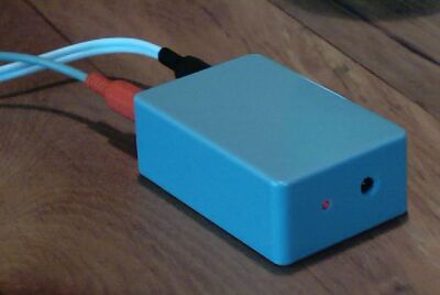
The unit is housed in a small "jiffy" box with holes drilled for the IR receiver and feedback LED on the front, and the sockets for power and TTL level output on the back. The TTL level output is then connected to the IR input on the back of the NAD T752 amplifier, and feeds it the IR signals received.