 The low level electronics installed
All of the electronics, other than the Loudspeaker protection circuit, are based on Rod Elliott's projects at ESP. I have used either the complete projects, or ideas from the following projects:
Project 05: Preamplifier Power Supply
Project 09: Linkwitz-Riley Crossover
Project 71: Linkwitz Transform
Project 38: Signal Detecting Auto Power On Circuit
Project 68: 300W Subwoofer Amplifier
The first four projects make up the low-level preamplifier section, which consists the signal detection, crossover, and Linkwitz Transform for equalization of the bottom end. These are powered using the P05 Power supply. I ordered the PCB's for the supply, crossover, and transform circuits, and built the signal detection circuit on prototype board. Each of these PCB's are well layed out, and come with good instructions on the best way to populate the board and how to incorporate it into the system. I can heartily recommend these boards. They are simple to put together, perform extremely well, and are very reasonably priced, so if you are thinking of building one of the above projects, I would certainly suggest you purchase the PCBs! Not only do you get a great product that will simplify the building tremendously, but you also get advice and assistance from the designer.
Layout of the system is done as follows. The full stereo signal gets input via RCA connectors directly into the P09 Crossover. The Hi-Pass signal is then sent to RCA's for output to the main amplifier, and the Low-Pass signal is mixed together via 22k resistors and sent to the Linkwitz Transform circuit. The right input signal is also sent to the signal detection board which switches the mains power to the subwoofer amplifier.
The P09 board is configured as a stereo 24dB/octave Linkwitz-Riley crossover at 80Hz. The trimpots and feedback resistors in the high pass buffer stage have been eliminated, so there is no gain at all in the high pass section. In the low pass section, I've replaced the trimpots with a dual gang linear pot so the gain is accessible from the back of the unit, and have replaced the resistors to ground with lower values to increase the range of gain possible. (R6 changed to 1k, and R7 changed to 2.2k) This gives a range of -11dB through to +15dB, which is more than enough to match different amplifiers (and to increase the gain to show off the sub!). The 100R output resistors in the low pass section have been replaced with 22k resistors and then the signals are summed before passing through the output coupling cap. I have since added a bypass option by taking the volume pot lead from the B-connections on the P09 board, instead of the A-connections. This allows any input to bypass the lowpass crossover altogether - ideal when one is using the in-built Linkwitz Riley 4th order lowpass filter built in to an AV Receiver.
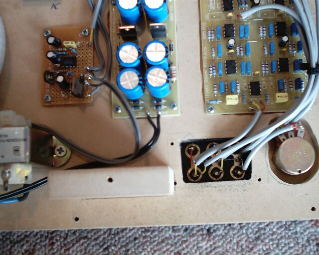
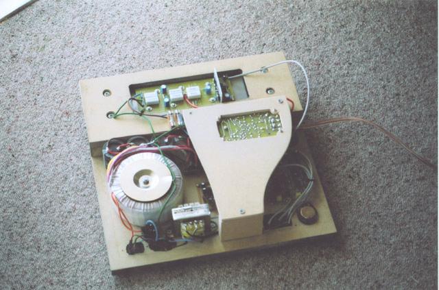
Of paramount concern in a subwoofer application is grounding, and power supply runs - especially when you consider there is a fair bit of gain at 50Hz. I layed out the amplifier in such a way as to minimize as much as possible mains power runs, and so as to maximize the distanct between low-level signal lines and AC power lines to reduce noise. Also, all signal lines are grounded at one end only to avoid ground loops. Here is a picture of the layout of the low level section. Note that the Linkwitz Transform has yet to be installed (It goes in the section between the two switches at the top) and the line from the right input to the signal detection board (the small one) is also not present.
The low level electronics installed
This is the second amplifier I have built (The first being an LM1875 based stereo amp for the computer satellites) and had a mostly enjoyable time building it. The PCB supplied by Rod is excellent, and the instructions supplied are easy to follow and cover everything in good detail. I would recommend you purchase the PCB if you wish to build this amplifier. It is designed so that the output transistors mount on the underside of the PCB, and this simplifies the building considerably, as they all the output transistors can be bolted at the same time to the heatsink. I can testify that if you follow his instructions carefully you will produce a fine amplifier!
The board itself is nicely laid out with the voltage amplification stage and class A driver stage being tucked neatly down one end of the board, and the output stage occupying the rest of the board. The traces on the output stage are nice and solid, which turned out to be a great asset as is described below. It took around an hour or so to populate the board, and again Rod's guide (available when you purchase the PCB) has a logical procedure to follow.
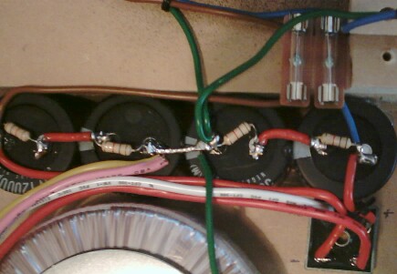
Power to the board is done as in the schematic on Rod's site, and is straightforward. The transformer is a 40-0-40V 300VA unit from Jaycar, and this is fed to a 35A bridge rectifier, and 6000uF of capacitance per rail. The filter caps consist of 2 12000uF 50V computer graded electrolytic caps in series (As the DC supply for the amp is over 50V at around 56V). I have used 5k6 resistors in parallel with the caps in order to balance the voltage across them. The formula to work out the ideal resistance for a given capacitance is R=1/(0.15*C).
 The power supply
The mains (hot) wire is triggered by a relay operated by the signal detection unit. Mains is fed in via a 3A slow blow fuse and an IEC socket. The DC lines to the amplifier are connected via 5A fast blow fuses for protection.
The grounding technique is the classic star earth at the centre tap of the filter capacitors. Mains earth is connected at this point. Other grounds are then taken to the amplifier, and to the heatsink (In case of insulator fault between the output transistors and sink).
I had no problems at all building the amplifier, and it tested out perfectly. Make sure if you build it that you hook up the power supply initially with safety resistors in series! I did, however, have a few problems once a 4 ohm load was powered. This was due to the output transistors I originally purchased being fakes! The moral of the story is:
DO NOT PURCHASE OUTPUT TRANSISTORS IF THE PRICE SEEMS TOO GOOD TO BE TRUE!
There is a very high likelihood that you will get counterfeit transistors! I purchased Toshiba branded 2SA1302's and 2SC3281's from a supplier here in New Zealand, and the 2sa1302's turned out to be fakes. This resulted in the amp failing several times, and several more output transistors needing to be purchased. I ended up buying 5 2sa1302's and 4 2sc3281's before the fact they were fakes became apparent. I am thankful to Rod Elliott for helping me out by performing an SOA test on a pair that I sent him for confirmation. I also popped several of them open (By compressing them in a vice to crack the epoxy packaging) and, sure enough, the dies were too small for the parts to be genuine. I have detailed photos of the fakes here. Needless to say, this has caused much disappointment that goes beyond just the financial cost (Which is not insignficant). The board took a bit of a hammering due to the constant soldering/desoldering of the output transistors, and I ended up having to patch a few of the traces. Luckily most of them are nice and solid, so the patching was easy to do. It doesn't really matter too much, as the output section of the board is really only there to aid in transistor mounting.
I ended up acquiring some genuine MJL21193/4 pairs from OnSemi directly, and have had no further problems. With the genuine output transistors installed the amp produces a LOT of power quite comfortably into a 4ohm load. If you wish, you can also add an extra 4 output transistors as described on Rod's page, but I didn't bother. It goes plenty loud enough for me, and doesn't need the extra transistors, as subwoofer use implies intermittent duty. Here is a photo of the completed P68 amplifier board.
 P68 amplifier board installed
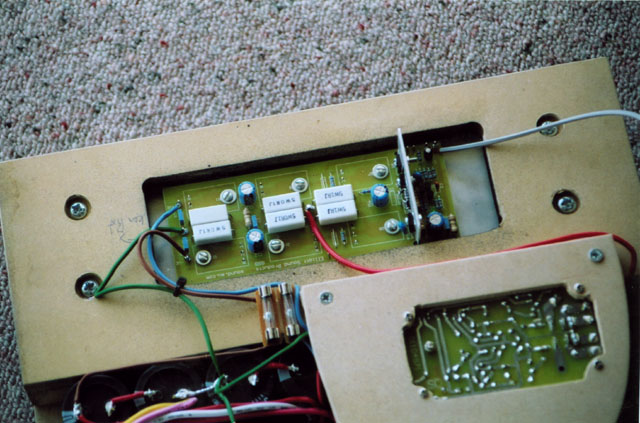
As can be seen in the image below, I have added a Loudspeaker protection circuit. This was a kit purchased from Jaycar on special, and disconnects the speaker immediately there is DC present on the output of the amplifier (ie a fault). This saved the speaker from the 3 times the amplifier blew due to the fake transistors. It was well worth the $30 I paid for it, considering the driver was $300.
 Amplifier and with Loudspeaker Protection circuit
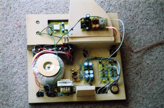
And finally some pictures of the completed amplifier module. The outside is spray painted with black gloss enamel, and the wohle unit will be recessed into the rear of the subwoofer enclosure.
 The finished amplifier.
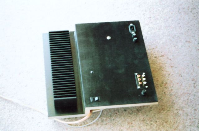 Rear view of the amplifier module.